A common actuator in control systems is the DC motor. It directly provides rotary motion and coupled with wheels or drums and cables can provide transitional motion. The electric circuit of the armature and the free body diagram of the rotor are shown in the following figure.

The motor torque T, is related to the armature current, I by a constant factor Kt. The back emf, e, is related to the rptational velocity by the following equations.
T=Kti
e=Keθ
From the figure, we can write the following equations.

Where,
J=moment of inertia of the rotor.
b=damping ratio of the mechanical system.
K=Kt=Ke=electromotive force constant.
R=electric resistance.
L=electric inductance.
V=source voltage.
θ=position of shaft.
Mathematical Analysis:
Using Laplace transforms on the above modeling equations, we get

MatLab Code:
clear all;
close all;
J=0.01;
b=0.1;
K=0.01;
L=0.5;
V=20;
figure;
for R=2:2:10
num=K;
den=[(J*L) ((J*R)+(L*b)) ((b*R)+(K*K))];
sys=tf(num,den);
step(V*sys);
hold on
grid
title('Step Response for the Open Loop System (DC Motor) When R is Varied');
xlabel('Time')
ylabel('Speed');
end
figure;
R=10;
for V=4:4:20
num=K;
den=[(J*L) ((J*R)+(L*b)) ((b*R)+(K*K))];
sys=tf(num,den);
step(V*sys);
hold on
grid
title('Step Response for the Open Loop System (DC Motor) When V is Varied');
xlabel('Time')
ylabel('Speed');
end


MatLab Data:
| Resistance (R) | Voltage (V) | Rise Time (Tr) | Settling Time (Ts) |
| 2 4 6 8 10 | 20 20 20 20 20 |
|
|
| 10 10 10 10 10 | 4 8 12 16 20 |
|
|
Report:
Determine the maximum speed that the motor can achieve and time to reach that speed when 1 volt is applied?
When 1 volt is applied and when resistance is 1 ohm, maximum speed is 0.0996 unit and time to reach the speed is 2.8 time units.
How steady state speed and settling time of the output response vary with the variation of R and input voltage?
When Resistance was Varied:
· Steady state speed of the system increases with decrement of resistance and vice-versa.
· Relation of rise time to resistance variation has similar characteristics, i.e. they are inversely related, when resistance increases rise/settling time falls and when resistance is reduced rise/settling time rises.
When Input Voltage was Varied:
· Steady state speed increases with increase in input voltage and conversely.
· Rise/settling time is invulnerable to input voltage change.
Can you suggest any modification in the system if we want to increase the steady state speed and reduce the settling time simultaneously?
If we increase the input voltage and the value of R at the same time, we can increase the steady state speed and reduce the settling time simultaneously. But it contradicts two different ideas. Firstly it’s not wise to change resistance of a well built system and also not convenient economically. Secondly, when change in R and input voltage are related when it’s required to increase the steady state speed and decrease the steady state speed, a feedback loop is a must, which is a must for closed loop system but should not be present in an open loop system.
As the given system is an open loop system. It can’t provide any kind of process to increase the steady state speed and to decrease the settling time at the same time.
Discussion:
In this experiment, we studied modeling of physical systems and their open loop response.
Describing a System:
The systems are usually dynamic by nature, one such model relating the input and output is the linear, time variant differential equation.
Use of Laplace Transform:
However, the classical approach of modeling linear systems is the transfer function technique which is derived from the differential equation using Laplace transform. Transfer function yield more intuitive information than the differential equation by visualizing the effect of system parameter variations on the system response as well as it eases the modeling interconnected systems.
In our experiment, we modeled a cruise control system and a dc motor and also studied their open loop response. We used software simulation (MATLAB) for this purpose. We also studied how the response changed with the change of different variables.
Open Loop System:
An open loop system utilizes an actuating device to control the process directly without using feedback. Here the final output is not compared with the desired one.
Block Diagram of Open Loop System:

Advantages of Open Loop System:
· Reduction of cost
· Simple
· Control is easy
Disadvantage of Open Loop System:
· No compensation for disturbance.
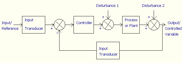
Closed Loop System:
A closed loop control system uses a measurement of the output and feedback of this signal to compare it with the desired input.
Block Diagram of Closed Loop System:
Advantages of Closed Loop System:
· Greater accuracy
· Less sensitive to noise, disturbance and changes in environment
· Control is more convenient and flexible
Disadvantages of Closed Loop System:
· Costly
· Complex system
· Sometimes unstable
No comments:
Post a Comment